Future Weather–Is Wind Worth it or Does the Sun shine Through?
I’ve been doing a lot of thinking about just how much power we are going to need to live a full and trouble free, zero carbon lifestyle in Spain. You’ll have gathered from some of the other posts that the energy principle that I’m following is “no carbon brought to the land”. If it’s here already then it’s fair game – and, no, we haven’t struck oil. I’m thinking of wood from trees and water from the ground although there’s not a lot of carbon in water, but I just don’t want to cave in and use gas or oil to cook and heat and I’d really rather not have a backup generator if it’s avoidable.
For starters, a decent 10KW diesel generator will set us back several thousands pounds in capital costs plus fuel over the years both of which could be better spent on other sources of energy. I’ve calculated that 15KW of solar panels will give us a huge abundance of energy in the summer and by using my automatic panel angle adjustment system I should be able to optimise the power that’s available in the winter. Clearly, the colder season is when we get the least sunlight so making best use of what energy there is is the key to success.
If you’re bored one day, type “off grid” or “off grid living” into Youtube and have a look at what other people are doing. There are a serious lot of preppers and hippies out there! The preppers are generally happy embracing technology, but the hippies tend to shy away from it apart from, I notice, the use of gas for cooking and showers plus Apple Macs, for some reasons. Amateurs! Electricity is the way to go. Or wood if you’re a masochist and just looooove cutting and hauling trees.
Some tests I did last summer (http://www.offgrid.casa/testing-solar-panels-in-the-uk/) when we finally managed a couple of sunny days in Northumberland, showed that we can potentially get around 80% more energy from the same panels if we adjust their elevation angle throughout the day.
However. Having spent a week in deep snow in Matarranya in February, it’s clear that there are periods when the sun simply hasn’t got his hat on and is unwilling to put in anything but a fleeting appearance. Yes, there will always be some light but if it’s as pale and wan as a teenage goth after a breakup with his girlfriend then it could be a small fraction of what’s actually needed, especially on long, cold winter nights. So, what to do?
There’s another source of zero-carbon zero-cost power available of course. Wind is often more prevalent in the winter than in the summer, but exactly how much?
True to form, rather than taking the easy route I decided to design another gadget. This one is a neat little device that measures solar and wind power on a minute by minute basis. It also takes readings of temperature, pressure and humidity as a by-the-by. It occurred to me that having all of this data logged over the next year might give me an idea of how much combined solar and wind power I could expect over a 12 month cycle.
With a bit of Google “research”, I reckon that the best type of of wind genny is the horizontal type. To those with an engineering disposition, reducing the stress on moving parts of a machine is always a good idea. The traditional Dutch style windmill with vertical blades have a huge amount of shearing stress on the bearings which hold the hub and hence the blades. The hub and shaft are horizontal, so the weight of the blade assembly is trying to twist the whole thing downwards to rip the windmill apart. If you are of a voyeuristic leaning, have a look at these youtube videos and be prepared for the shocking truth about wind power – Notice anything?
Yes, all of the catastrophic fails are of the Dutch style windmill.
Horizontal wind generators have the advantage that all of the weight of the blades and turbine assembly is acting straight down where the bearings are located. In theory, there’s nothing stopping you from using magnetic or even mercury bearings to avoid any real wear.
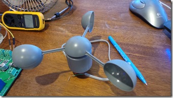
So, I ordered a little horizontal anemometer from Maplin Electronics who, as I write this, are in the process of going bust and have a huge sale on. So, mercenary that I am, I took advantage and bought the complete stock of our closest store, which amounted to four, 3-cup twirly wind measuring devices for the princely sum of £1.74 each.
With a small amount of destruction and the sacrifice of one unit, it became apparent that the sensing device in these devices is nothing more than a simple reed relay which is opened and closed by the action of a pair of small magnets as the vanes rotate.
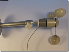
So, simply counting these pulses in a fixed time period would give an indication of wind speed. In the Maplin case, there are two pulses per rotation. The distance travelled in each rotation is 2Πr so in theory the distance travelled in one rotation per second would equate to the wind speed. However, it turned out to be a fraction of the actual value. If you look at the top left of the anemometer picture, you can see a little, cheapie yellow and black, Ebay hand held wind speed meter which I used to check this. I set up a small desk top fan that we use to keep cool when we’re travelling to give me a constant wind speed and it became apparent that my measurements were in fact out by a factor of two or three.
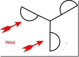
Hmmm. What was going on? I came up with a theory, correct or not it appears to fit the facts. The wind acts on both sides of the cups of the anemometer, but as one side is convex and the other concave the effects are asymmetrical, so the vanes only turn in one direction. As the vane turns, one cup will face into the wind as another one is catching it, but the surface is curved and streamlined so the drag is reduced.
All of this leads me to realise that the anemometer won’t turn at the same speed as the wind is travelling, so a fudge factor needs to built in and this is what I did.
A little bit of experimentation led to a fudge factor of 3.16, which is suspiciously close to the value of the universal constant Pi (3.14159). I surmise that there’s an equation to correlate the rotation of these anemometers to wind speed and it includes a Pi factor which I’m missing. However, hey ho, it works and seems accurate enough for government work, so it’ll do me just fine.
So, the circuit incorporates a display so that I can see what’s going on and check what’s happening with power, wind and environmental variables such as temperature etc. I also put on a couple of buttons so that I toggle between displaying the current instantaneous values and some simple graphs of temperature, pressure, humidity, various solar and battery power readings and the wind speed.
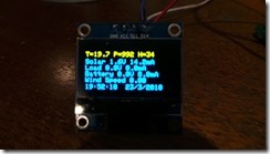
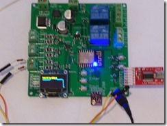
Here’s the final weather station circuit board and the display showing the basic solar, weather and wind information.
Note the two blue relays on the board. These are in case I want to be able to turn anything on or off – e.g. an infra red flood light for nocturnal animal observation with the webcam or to reset anything that needs it’s power cycling. I’m thinking of a getting a T-Shirt with “Have you turned it off and on again” as that’s what I say to the wife pretty much daily when something doesn’t work.
Mounting the Anemometer
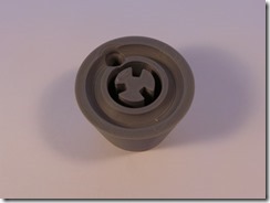
I needed something to hold the anemometer in position and to be able to level it to the horizontal, bearing in mind that all of this kit is going to be mounted in Spain on a 400 year old roof beam that I’ve stuck in the ground and tethered with some fencing wire. Resorting to Ebay, I found a wall mount for a camera for about £3 which looked like a likely candidate. However, it has a standard camera screw mount and my anemometer is actually a replacement part for some random, Maplin weather station so the two are not in any way, shape or form compatible. Thankfully, my trusty Robox 3D printer came to the rescue…plus half an hour on a CAD package – resulting in the little conical mounting bracket shown here.
The odd sort of cross shape in the middle matches up with the base of the anemometer and I’ve even put a cable hole in to stop the wires from fraying in the wind. The whole thing then screws onto the camera bracket and off we go with an easily levelled wind speed measuring doohickey.
What did I ever do before 3D printers were invented?
So, now the hardware is finished, I need to mount the lot on a roof to test it all out , make sure that it’s reliable and check that my software gives me everything that’s needed.
Leave a Reply
You must be logged in to post a comment.