Helen has been away with a friend in Crete for the last few days, so it’s given me some time to bring a few solar ideas together. I built the prototype interface circuit board for my PIP4048 solar charger/inverter and discovered a better way of doing one or two things, so I decided to re-design the circuit board. Amongst other things, I decided to change the ethernet network interface to a different chip, moving from the Wiznet W5100 to the much better W5500.
I also separated out the way I bring in the data from the solar power monitor as there was a issue with it sharing a data connection with the W5100 network chip and even though I’m going to use the W5500, I wanted to be sure. Safety first.
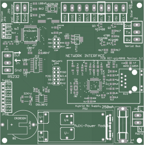
PIP4048 Monitor PCB
I’ve had a go at laying out PCBs for network interfaces in the past, but for some reason, I’ve never managed to get them working. So, to save me any potential bother, I’ve also put on a 10 way connector just in case I have to use an off-the-shelf network interface. You can see the network circuitry on the right hand side, middle of the PCB, surrounded by a white box.
I also thought that it would probably be a good idea to add a fuse, just in case! You can also see a round object in the bottom left hand corner, this is a battery to run the real time clock which is there in case the unit loses network connection and can’t access the current date and time from the internet. This is needed to calculate the solar panel angles throughout the day.
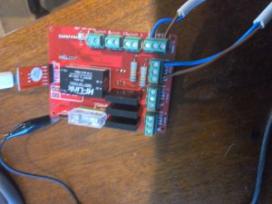
I’ve also finalised the design for the solar panel tracker. If you’ve read the other posts, you’ll know that I’m using cheap, 12 volt linear actuators to change the angle of the panels throughout the day. Here’s the PCB.
solar tracker
I was originally going to have nine solar panels in one huge array, all being adjusted by a pair of linear actuators. This turned out to be rather cumbersome and would have required a pair of laser sensors to make sure that the frame holding the panels wasn’t twisting. Much as I love the little laser distance sensors, I realised that a much more straightforwards way of doing things would be to have only three solar panels on one frame and a single linear actuator to adjust them.
I’ve picked up a pair of gas struts from Ebay which are meant as a replacement for the rear hatch of some car or other, but they’ll each lift 60KG, so one of those plus the linear actuator should be quite adequate to lift up the 70KG or so weight of three panels plus the frame. I’ve also ordered a pair of 150mm stainless steel, ball bearing hinges to allow the panels to be fixed at the base and to rotate as the actuator moves in and out. I’ll post some pictures when the first three solar panels turn up.
The solar tracker design will handle up to three sets of three panels independently movable. You can see on the PCB design above that there’s a 4-way connector at the bottom left marked “solar panel”. I’m using 4-way lighting switch cable as it’s real cheapo stuff and easily available. The idea is that I’m only going to move one set of panels at a time, so I’ve allocated a wire which is common to all three panels’ linear actuator. Then, I can just use one of the other three cable cores to power each of the individual actuators.
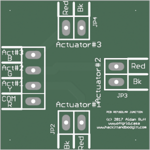
solar junction board
I guess that the main point of all this is that I can put the solar trackers inside the battery/inverter house out of any weather and just run out a cheap, 4-core cable to a weather proof junction box beside the panels. Oh, and I was on a roll this morning so I decided to do a little three-way junction board to save me having to mess with choc bloc connectors when I wire the panels up.
The four way connector on the left brings the control power from the solar tracking unit in the battery shack and then it’s just simply split into three, 2-way connectors to hook up to the linear actuators.
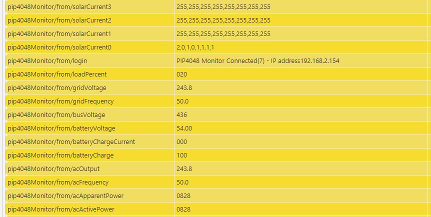
data from pip4048
I haven’t finished all of the software to run all these boards yet, but I do have all the basics in place. So, the PIP4048 monitor board is talking to my house network and the Raspberry Pi that runs everything and is also currently plugged into the PIP4048 inverter/charger via an RS232 serial line. It reads various parameters from the PIP every 10 secods – things like total solar charging power, battery power available and total power consumption.
Above, you can see an extract of some of the data monitored via the MQTT protocol on my Raspberry Pi. The top four lines show up to 32 solar panel current values. In fact the first three sets show ‘255’ eight times as they aren’t actually connected to anything. The 4th line shows that there’s a small amount of current, between 100mA and 200mA going through each of the eight solar current monitors lines.
The rest is fairly self evident. I’m running a my workshop heater via the PIP so ‘pip4048Monitor/from/loadPercent ‘is showing 20% of maximum load as it’s a maximum of 4KW and I’m using an 800 watt heater. In fact, the bottom value is ‘acActivePower’ which is showing 828 watts so that matches up pretty well.
The other stuff is mainly to do with battery charge current, battery level etc.
So, as you can see, I’m fairly close to having a complete solar control and monitoring system for the offgrid casa!
Recent Comments