This is just a test
Our Solar Powered Dream
Category: General (Page 1 of 2)
Off grid house in Spain
Testing Solar Panels in the UK
Is it all worth it? I mean really?
In order to convince myself that it’s worth all the hassle and cost of making my solar panels self-adjusting, I thought that it would be a rather good idea to see what difference there would be in power output by changing the angle of the panels in a real life situation.
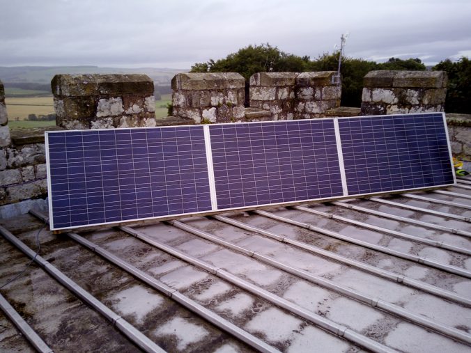
So, despite the almost constant rain here in Northumberland this “summer“, I managed to find a vaguely dry day on which to set up a bank of three panels on the flat roof of our Pele tower. This roof is covered with zinc sheeting and is like an ice skating rink when it gets even slightly damp. As there’s been more-or-less a lake up there for the last couple of months, I’ve avoided going up there like the plague in order avoid killing myself. However, there are now finally three panels in place. Fortunately, getting up there is reasonably easy even though it’s up a 1000 year old, medieval spiral staircase and the panels only just sqeeeeezed through. Clearly, they were planning more for defense against armed marauders than manhandling large aluminium and glass panels up on high. Who would have thought it?
On The Roof
I constructed a light, wooden frame to hold the panels and attached the linear actuator and a pair of 400 newton (40 Kg) gas lift struts. The first time I attempted to adjust the panels using the linear actuator, it became immediately apparent that the struts lifting capability was way too much as the panels started to warp as the actuator and struts fought against each other. So, on to Plan B when we get a break in the weather.
This consists of fitting four smaller, 100N (10Kg)struts, spaced equally along the array to give an even lifting assistance to the actuator. I figure that four struts will also help greatly in stabilising things if it gets a bit windy. I also fitted a small length of 50mm x 50mm, 3mm thick steel angle iron to the junctions between the panels to give them more rigidity and to reduce any potential bending or warping of the panel frames. One additional advantage of the smaller gas struts is price. The larger ones are about £18 per pair, whereas the small ones are £1 each, even though I’ll probably need to use all four, that’s quite a saving when I’m putting up 18 solar arrays.
To do my tests regarding adjusting the panels throughout the day to track the elevation of the sun, I need a totally cloud free day. Hey, it’s August in England, you’d expect a bit of sun occasionally wouldn’t you? Well, you’d be wrong! So far, I haven’t been able to carry out any tests whatsoever, other than putting what meagre amount of power is penetrating the clouds into my batteries. Who wrote that autumn is the season of mists and mellow fruitfulness? Well, we’ve had the strawberries, the red currants, the black currants, the gooseberries and the plums, so lots of mellow fruitfulness there. We’ve had/are having the mists and the rain, so is summer in the UK actually now autumn?
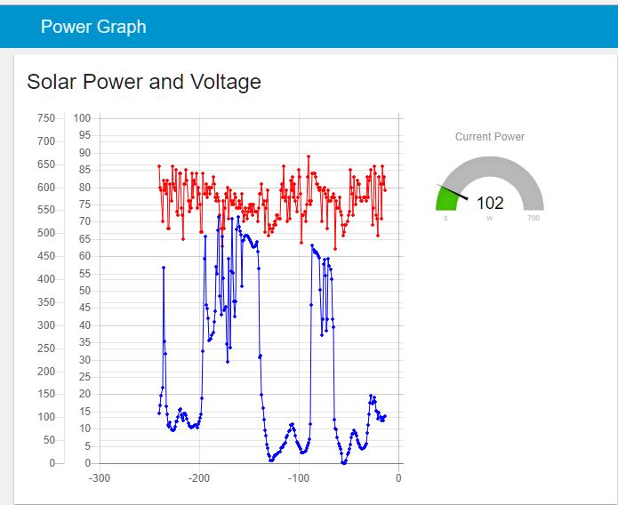
Solar Power and Voltage Output
Power, At Last!
The graph on the right shows the power from the panels for the last four hours. The blue graph is the electrical power being generated and the red one is the DC voltage of the array. I find it interesting that the MPPT solar battery charger inside the PIP4048 inverter/chargers only takes just as much power as the panels will give, so the voltage stays within a reasonably constant range.
There keep on being brief periods when the sun peeps out from behind the clouds, just to see if we’re wet enough down here. A couple of hours ago, for one gloriously brief moment, I was getting 536 lovely watts surging down the wires from the roof into my circuit cellar. In theory, in decent sunlight, I should achieve up to 745W, but so far no joy, no way.
My aim (dream!) is to have at least one totally, gin clear day so that I can log the power generated at different angles of the panel. Clearly, when they are face on to the sun, that should be the maximum power point. I have incorporated the ability in my little solar panel tracking units to be able to over-ride the automatic tracking facility and just force the panels to any desired angle.
Deluded?
This will mean that I can assess the different angles that people use for their boringly, fixed arrays and see how much extra juice they’d have to play with if they were to install trackers. Well, that’s the theory anyway and until we get some proper sunshine, that’s where it it’ll stay – in the land of untested theory.
Updates
I’ll update this post when or if the weather improves and I can get out onto the roof without risking life and limb, hopefully with some pictures of the final setup with the new gas struts.
Update – Sunday Afternoon
We had a brief gap in the rain, so I managed to get a couple of outside jobs done and then got up onto the roof for an hour or so before the heavens opened once more.
Here is the result of connecting three 24 volt panels end to end, giving me in reality between 70 and 90 volts depending upon the sun or lack thereof (more likely at the moment). I’ve bolted the frames together and then put some 50mm x 50mm steel angle iron along the tops to stiffen the whole thing.

A 3-way solar array
You can see that I’ve mounted them in sort of landscape format rather than the usual portrait layout you often see in solar farms in the countryside. The reason for this is that those panels you see dotted around in fields are on fixed frames, so they are stiffened at both ends making them more stable. I only want to use one linear actuator mounted in the middle of the central panel rather than one at either end, just in case one of them failed, I don’t want the array to be warped by the still functioning actuator and the panels potentially cracked.
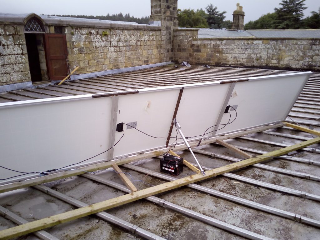
Back of the Solar Array
Below you can see the back of the array. There’s a stiffener (steel angle iron) which I’ve mounted in the centre of the middle panel to allow me ato attach the linear actuator. This at least means that the forces across the array are fairly constant and therefore less likely to crack the panels as they are being adjusted.
You can see the small 12V battery that I’ve using to run the actuator whilst setting everything up – it allows me to extend and retract the actuator to check that everything is working. Once I’m happy with the design, I’ll throw a cable down int the light well which is to the right of the picture over the wall and down into my workshop where all the magic is happening.
Here’s a closeup of the actuator – you can see that the way that I’ve mounted it makes it look like it’s upside down.
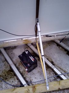
The Linear Actuator
In fact, having the motor at the top and the piston pushing down helps to reduce the potential for dirt or water getting past the seal. There’s also a lubricating mechanism inside which only works when it’s this way up.
I’m considering putting some kind of water proof fabric shield over the whole of the back of the panels to protect cables, actuator and gas struts from the dust and weather, however putting the actuators and the struts the right way up is a good start anyway.
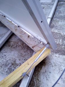
Gas Strut Installed
I installed two of the 100N gas struts – you can see one of them at the end of the panels above – but, I don’t think that they’re quite meaty enough for the job as I had to mount them at quite a shallow angle so that their limited travel wasn’t a problem as the array moves. Never mind, I’ve got four 200N versions winging their way from Hong Kong as I type. So, four of these little beauties should in theory give me about 80KG lifting capability which is more than the array which weighs in at 60KG. However, due to the position and angle that I’ve placed them, I’d be surprised if I get more than about 20KG lift which is just enough to stabilise everything in strong winds and to reduce the load on the actuator.
Solar Farm
Things are getting very exciting now as we have the final plans for the house and we’ve been to see the local major to get his opinion, which was very favourable thankfully. Amongst other things, we’ve agreed the location of the solar farm with Fernando the builder who is going to build the garage, the battery/inverter shed and put in the concrete bases for the panels.

The Solar Farm In Spain
You can see from the diagram on the right that the solar farm will be about 200m from the house. The cables from the panels will all go into a shed which will house the batteries,the charger/inverters, my monitoring and control electronics and a backup generator just in case of really bad weather in the winter.
Update on the first “sunny” day for months
All I needed was a bit of consistent weather for my comparative solar tests and I’ve been waiting weeks to get it. Well, finally today was the day! I’ve had a window of opportunity lasting for over two hours now where the sun was shining. Well, I say “shining”, but there is a lot of high level cirrus cloud probably indicating an approaching weather front, so it’ll probably rain again tomorrow, or it may be sunny. Who knows?
Anyway, the point is that it was at least consistent and whilst I didn’t get as much power as the panels are capable of producing, I could see what difference angling them to the sun made to their output.
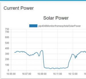
Solar Power Graph
As you can see from the power graph here, at around 16:05, there was around 360W being produced and the tracking unit had set the panels fully face on to the sun. I then adjusted them about 30 degrees away from optimum and the power dipped by around 90-100W just after 16:07. I then brough the panels back through the optimum position and up to the maximum angle of around 80 degrees, in other words almost vertical and the power output plummetted to around 50W!
I wasn’t expecting that much of a drop, I have to say. I then let the panels be set back to the optimum angle by the tracking unit and the output went back up to just short of 400W.
So, it looks as if tracking the suns elevation is definitely worth while as it can make a huge difference to the power output.
This is exactly what I wanted to find out, so the question has been answered, it does look as if it’s worth while adjusting the panel angles throughout the day and throughout the seasons.
Happy days.
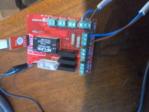
Well, I’ve designed the printed circuit board (PCB) for the solar panel tracking system and the prototype hook up on the bench appears to work very well, although I’m waiting for some new gas lift struts to work with the linear actuator to take the load off the motor.
However, here’s a clip showing the bits and bobs that I’ve tinkered together
And here’s another clip of it in action
We’re going over to Spain again this coming weekend to meet the builder and to actually poke some marker sticks into the ground showing where we want to place the workshop/garage, the solar panel bases and the little shed which will house the batteries and inverters, so it’s nice to see some progress.
At the moment, I’ve just screwed the panel and actuator to the floor in my workshop, however I’m intending to bolt the stuff directly down to the concrete bases that will be poured in a few weeks time with a little bit of luck. The first pair of gas lifts struts that I bought from EBAY were dirt cheap, but like anything cheap you get what you pay for! Unfortunately, the struts aren’t adjustable so both struts give a total lift of 120KG so it’s way too much for my panels which weigh in at 20Kg each or a total of 60KG.
Of course, there won’t be a force of 60KG or 600N on the linear actuator which is capable of lifting 150KG, but there will probably be of the order of 50KG load when the panels are lying nearly flat. The gas struts will also help to give the panels some stability in the wind as they’ll be attached to either end, whilst the linear actuator will be placed centrally to the panels, which are about 160cm long. So, I’ve ordered a pair of 20KG (200N) struts from The Strut Depot, which sounds American but really isn’t. These should take the majority of the load off the actutaor whilst leaving enough load for me to detect the current being taken so that I know when the panel has stopped moving. This is essential as the way in which I will set the angle of the panels is by timing the movement of the linear actuator from end to end and then estimating the distance required for each angle during the day..well, that’s the theory! So far, it seems to be holding up…
In the videos you can see some of the circuit boards that will connect to the PIP4048S solar charger/mains inverter together with the 8-way solar panel power monitor. These also connect to the panel tracking units to allow me to monitor them for faults and to pass information such as the date and time across to the trackers – this obviously needed for the trackers to position the panels at the correct angle at the appropriate time of day. I’m not relying on any kind of sensor to locate the sun as that could cause issues when it’s cloudy and I don’t want the panels hunting for the sun unnecessarily.
You can see in the video clip that I’ve decided to lay the panels on their side, effectively in landscale rather than portrait mode as, again, I want them to be less susceptible to wind.
Lastly, the hinges that I’m using are ball bearing hinges intended for very heavy doors. I intend having three hinges per set, one hinge at the outer edges of the panels and one directly in line with the linear actuator in the middle of the central panel of the three.
It’s getting quite exciting here in Northumberland as I’m actually seeing the stuff coming together. Now all I need is another 51 panels and 6 sets of control electronics, 18 linear actuators and 36 gas lift struts and Bob’s your Auntie! (we’re equal opportunities Up North and if Bob wants to be an Auntie instead of an Uncle, that’s his right).
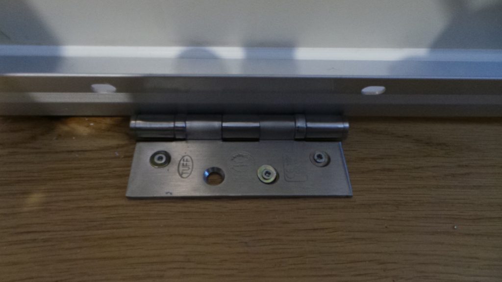
Ball Bearing Hinges
The hinge that I’ve selected is just a 100mm, ball bearing hinge that would be used on a very heavy door and so should be fairly long lived. Oh, and it’s stainless steel. Everything is going to be stainless steel as I don’twant rusting anywhere.
You can also see some of the other circuit boards in the viceo clip including the interface to the PIP4048s solar charger/mains inverter and one of the 8-way solar power monitoring boards.
Onwards and upwards
STOP PRESS – Update!
Here’s a neat little excel spreadsheet that I’ve tinkered together to check the maths for the angle of the solar panels. Just type in the time e.g. 9.25 is 25 past nine, the date and the latitude of your installation and the final box will give the angle of the sun above the horizon. Don’t adjust for summer time as it actually needs solar time.
So, I’m working on the software to go in my solar tracking circuit that will use a light sensor to measure the length of the day and then make an approximation of the date and time and use that to track the sun… Fingers crossed!
Latest Update – 4/9/2017 – GPS Updating
I had a brain wave and realised that if I plugged in a satnav GPS module then I could get the latitude, longitude, time and date. From all that, I could then derive the time zone and thereby calculate the solar panel angles, all without setting up anything manually.
The result? Well, a $3 module plugged in and it works! I’ll update this with some pics when I get a chance. We’ve just had a power cut at home in Northumberland and I’m currently running on my test PIP4048 mains inverter and as the sun has gone down and it’s been raining all day, I don’t have a huge amount of power available.
Helen has been away with a friend in Crete for the last few days, so it’s given me some time to bring a few solar ideas together. I built the prototype interface circuit board for my PIP4048 solar charger/inverter and discovered a better way of doing one or two things, so I decided to re-design the circuit board. Amongst other things, I decided to change the ethernet network interface to a different chip, moving from the Wiznet W5100 to the much better W5500.
I also separated out the way I bring in the data from the solar power monitor as there was a issue with it sharing a data connection with the W5100 network chip and even though I’m going to use the W5500, I wanted to be sure. Safety first.
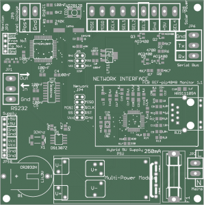
PIP4048 Monitor PCB
I’ve had a go at laying out PCBs for network interfaces in the past, but for some reason, I’ve never managed to get them working. So, to save me any potential bother, I’ve also put on a 10 way connector just in case I have to use an off-the-shelf network interface. You can see the network circuitry on the right hand side, middle of the PCB, surrounded by a white box.
I also thought that it would probably be a good idea to add a fuse, just in case! You can also see a round object in the bottom left hand corner, this is a battery to run the real time clock which is there in case the unit loses network connection and can’t access the current date and time from the internet. This is needed to calculate the solar panel angles throughout the day.
I’ve also finalised the design for the solar panel tracker. If you’ve read the other posts, you’ll know that I’m using cheap, 12 volt linear actuators to change the angle of the panels throughout the day. Here’s the PCB.
solar tracker
I was originally going to have nine solar panels in one huge array, all being adjusted by a pair of linear actuators. This turned out to be rather cumbersome and would have required a pair of laser sensors to make sure that the frame holding the panels wasn’t twisting. Much as I love the little laser distance sensors, I realised that a much more straightforwards way of doing things would be to have only three solar panels on one frame and a single linear actuator to adjust them.
I’ve picked up a pair of gas struts from Ebay which are meant as a replacement for the rear hatch of some car or other, but they’ll each lift 60KG, so one of those plus the linear actuator should be quite adequate to lift up the 70KG or so weight of three panels plus the frame. I’ve also ordered a pair of 150mm stainless steel, ball bearing hinges to allow the panels to be fixed at the base and to rotate as the actuator moves in and out. I’ll post some pictures when the first three solar panels turn up.
The solar tracker design will handle up to three sets of three panels independently movable. You can see on the PCB design above that there’s a 4-way connector at the bottom left marked “solar panel”. I’m using 4-way lighting switch cable as it’s real cheapo stuff and easily available. The idea is that I’m only going to move one set of panels at a time, so I’ve allocated a wire which is common to all three panels’ linear actuator. Then, I can just use one of the other three cable cores to power each of the individual actuators.
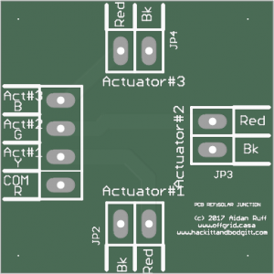
solar junction board
I guess that the main point of all this is that I can put the solar trackers inside the battery/inverter house out of any weather and just run out a cheap, 4-core cable to a weather proof junction box beside the panels. Oh, and I was on a roll this morning so I decided to do a little three-way junction board to save me having to mess with choc bloc connectors when I wire the panels up.
The four way connector on the left brings the control power from the solar tracking unit in the battery shack and then it’s just simply split into three, 2-way connectors to hook up to the linear actuators.
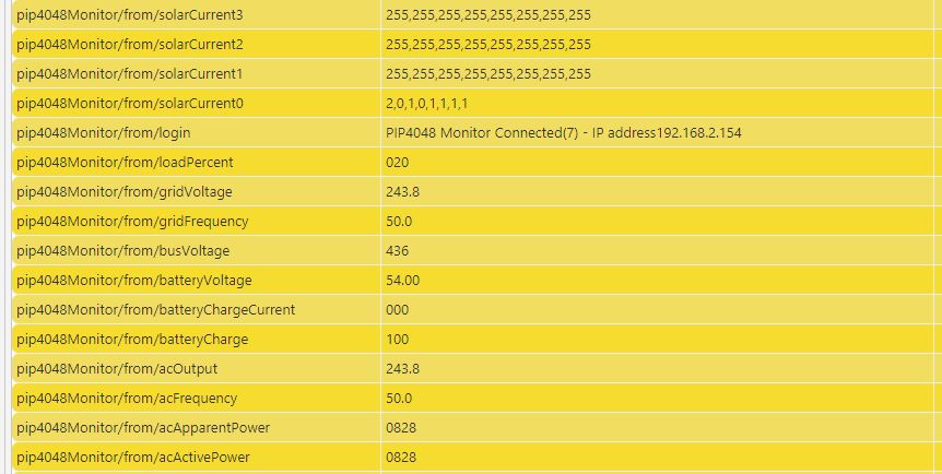
data from pip4048
I haven’t finished all of the software to run all these boards yet, but I do have all the basics in place. So, the PIP4048 monitor board is talking to my house network and the Raspberry Pi that runs everything and is also currently plugged into the PIP4048 inverter/charger via an RS232 serial line. It reads various parameters from the PIP every 10 secods – things like total solar charging power, battery power available and total power consumption.
Above, you can see an extract of some of the data monitored via the MQTT protocol on my Raspberry Pi. The top four lines show up to 32 solar panel current values. In fact the first three sets show ‘255’ eight times as they aren’t actually connected to anything. The 4th line shows that there’s a small amount of current, between 100mA and 200mA going through each of the eight solar current monitors lines.
The rest is fairly self evident. I’m running a my workshop heater via the PIP so ‘pip4048Monitor/from/loadPercent ‘is showing 20% of maximum load as it’s a maximum of 4KW and I’m using an 800 watt heater. In fact, the bottom value is ‘acActivePower’ which is showing 828 watts so that matches up pretty well.
The other stuff is mainly to do with battery charge current, battery level etc.
So, as you can see, I’m fairly close to having a complete solar control and monitoring system for the offgrid casa!
How do you turn a light on? Simple, of course, you flick a switch. What if you have lots of separate lights to turn on or off, well you walk around the house flicking lots of switches, surely?
You could go to the main circuit breaker and just switch all of the lighting breakers, but that’s a bit extreme. So, at the risk of re-inventing the wheel, I decided that the offgrid casa needed something new. How about networked lighting control?
I looked at existing houses and it’s unlikely that any one room needs more than three lighting circuits – say, overhead light, wall lights and maybe low level for mood lighting.
So, I turned to the trusy ESP8266 wifi processor that’s the basis of many of my projects and came up with a neat little design to handle three lighting circuits. Using a network linked device means that remote control becomes a possiblity.
Budding electricians amongst you know that in traditional lighting circuits, you can only have two switches on any one circuit as it becomes far more complicated to handle more than two. So, you end up with a switch on the wall as you walk in one door to a room and the second as you go out of another door.
What if you have three doors or want another switch at a more convenient location? Well, there are systems which allow you to have multiple switches using changeover relays – more commonly used in stairwells in apartment buildings. We press once for on and again for off. This is the system that I decided to use.
Three Way Lighting Controller
However, instead of a relay, the ESP8266 wifi processor has three inputs and three optically switched outputs, if you look at the picture above, you can see them at the top of the circuit board. There’s an input for the 240V mains and then three switched mains output on the right.
I decided to use opto-isolated triacs to switch the mains to the lights as they’re easy to use and safe. There are two versions – one which switches the mains at the point the AC signal hits zero (zero-crossing) and one that you can switch at any point in the AC cycle. Well, it just so happened that parts I had lying around my workshop were the zero-crossing type. These are great if you want to switch loads without inducing electrical noise in other devices, but if you want to dim lights they are as much use as a chocolate fireguard. Hence, a quick order to Mouser Electronics to fix what I initially thought was a software problem…many wasted hours in front of the keyboard!
So, the opto-switch that I ended up with is the Omron G3MC-202PL which is not expensive and is very neat.
At the time of writing, the board has the abililty to switch the three light output on and off and to set the brightness level. I can also send commands from my RaspberryPi using MQTT messages to change the intensity levels of all outputs. A short press on a spring loaded light switch changes from on to off, a long press cycles the brightness up and then down again. As soon as you release the switch the brightness level is remembered and then that is the ON level until you change it again.
Currently, we’re in Spain going through meetings with our architect, Manel, and our aperjador (structural engineer) Alfonso, so I haven’t been able to complete the software. However, an inspiration as I lay in the sun the other day was to allow the units to be linked together without a server so that they can work in a standalone situation.
This would be handy so that I could use one unit with as a master switch, say, near the front door of the house to turn all the lights off or restore them to their previous state which will be really useful if we’re going out for dinner.
So, each unit will have a list of other units that it can switch. Of course, these could be anywhere in the house or I guess potentially anywhere in the world it was felt that was useful!
I’ll add to this post as I get more of the software finished and also upload a video of the switches operating.
How do you find water without a geological survey and an orbiting satellite?
Simple. You bring in an 82 year old water diviner called Juanito! OK, OK! I’m not an ageing hippy, just ageing…
David, our agent, recommended that we employ the services of Juanito to locate water on our land as, whilst there are a couple of rundown porthos (wells) that we’ve found, the amount of water available is miniscule for modern living and certainly couldn’t be used for irrigation.
Yes, we can and will get water from the cisterna and borehole located about a mile and a half away, but there’s nothing like having your own water source to be properly off grid. I mean “off grid” means just that, doesn’t it? It doesn’t mean “connected to a community water tank up the road”!
So we met up with Juanito who is a very charming 82 year old and is fit as a fiddle. We met at the old house on our land and it was immediately apparent that he had already done his homework as he clearly knows the geology of the area intimately. He wandered around for an hour or so, going into each of our three valleys, before he settled on the middle one as the most likely candidate for water.
We stood and watched as he clambered across the hillside like one of our local ibex, a real mountain goat. He seemed to slowly zero in on the top corner, just below one of the tracks which leads down about half a mile from the house. We watched him quarter back and forth like a hound on the scent of a fox. Could he smell something?
He was carrying what looked like a y-shaped piece of hazel wood – in fact two bent twigs bound together with grey duct tape. Very scientific I don’t think and I didn’t expect much other than the usual pseudo-scientific mumbo jumbo.
Eventually, he waved to us from across the valley and I peeled Helen from out of the air-conditioned car as it was very warm. He then walked back and forth, holding his bent twigs and then indicated a spot. “There are two large water flows below us”, he proclaimed. “You have a huge amount of agua here, very lucky!”.
Apparently, he reckoned that the two flows crossed – one at around 165m and the other at around 190 m deep. I mean, 190m below us! How on earth? My skepticism must have shone like a beacon as he handed me the twigs and told me to have a go myself. I held the wooden water detector in the way he showed me and walked back and forth across the area and, blow me, the twigs practically tore my hands off! I couldn’t stop them from dipping no matter what I did and at the same point every time. Helen couldn’t resist having a go and the same happened for her. According to Juanito, only about one in 20 pepole can do it and it’s very unusual for both of a couple to be able to do it. Just lucky, I guess.
So, what happens next? Well, we have to pay around 8000 euros for the company that our divine water finder works with and they will use a pneumatic boring machine to drill a 20 cm shaft down to the water and line it with nylon sleeving to prevent collapse. We then drop a submersible, high pressure pump down the borehole and thar she blows…in theory.
So, I asked the obvious question; what happens if they don’t hit water? Well, said the man, you don’t pay a single euro. So, if it works, we have unlimited free water (about 20m3 per hour he reckons) and we pay; if it doesn’t, we don’t pay. Well, the company is still in business is all I’m saying.
How does it work, if it works? According to Juanito, there have ben 30,000 year old cave paintings discovered in the sahara showing people holding bent sticks like his. So, either they’re antennae to talk to aliens or they’re water divining rods. As he said, the primitive ancients couldn’t spare the resources to just keep on digging deep holes in the sahara desert to find water, they had to know where to dig – and dig they did, resulting in the lines of wells that have fed the caravanserai across the desert for millenia.
Unless of course, it was those pesky aliens spotting water from orbit?
Here’s a video of us locating the water – apologies for the slight blurriness.
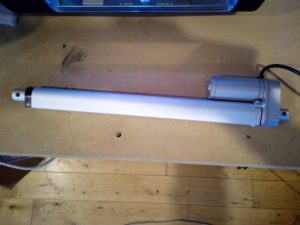
150Kg Linear Actuator
I received the first of the linear actuators that I want to use with my solar panels so that I can adjust them throught the day and the year to get the maximum amount of power from the available sun.
The actuator that I’m trying out first has 12 inches of movement and can push or pull up to 1500N or about 150Kg. Also, one of the reasons that I picked it is that it is – or at least claims to be – IP65 rated. This means that it’s meant to be resistant to dust and water sprayed onto it. It’s not submersible, but since we’re about 750m high, I think that lack of solar panel adjustment will be the least of our problems if we get a flood!
Over the next few days, I’m going to make a simple speed and directional controller. This will allow me to slowly accelarate the actuator and then reduce it’s speed gradually. This might seem to be a bit anal considering that the rate of movement is only about 5mm per second. However, when it’s under load and moving around 200 Kg of panels, I want to reduce any potential whiplash in the reduction gearing which you can hear whining in the video, as this will help to reduce wear and tear and, with a bit of luck and a tail wind, will increase the useful life of the actuator.
Here’s a video of it in action –

After a lot of research regarding solar chargers and mains inverters, I settled on the PIP4048MS from Mppsolar. This is a lovely device which can take up to 3KW of solar panels and will give up to 4KW of pure sine mains power at 230V.

The PIP4048MS
So, why did I choose this particular unit over the thousands of different pieces of kit out there in the market? Well, first it incorporates both functions of solar charger and mains inverter into one, second it’s also an MPPT charger, third you can parallel up to 6 units to handle up to 18KW of panels and give out 24KW of lovely mains power. This is more than many houses will get from their national mains grid.
Why do I need so much power? Well, my abiding principle is to have everything electric… Heating, cooling, cooking, hot water, the lot. I’ll have a bit to say in other posts about each of those elements as I develop the hardware to handle them
I guess that I’d better explain a few of those terms that I mentioned just now:-
MPPT
This stands for Maximum Power Point Tracking. What it means is that the solar charger will extract the most power that it can out of your panels and dump it into your batteries. In full sunlight, there’s not a lot of difference, from standard chargers, but as light levels drop towards dark or on cloudy days, you’ll get more power out of MPPT than other systems. In a nutshell, it briefly disconnects your panels from the batteries to allow the panel voltage to float to a higher voltage than the batteries and stores that power in a bank of capacitors. Then when there’s enough to be usable, it dumps it into the batteries and then starts again.
Other versions of MPPT use circuits called buck converters to give a higher, more usable voltage than would otherwise be available in low light levels leading to an even more efficient extraction of the energy from the available sunlight.
Pure Sine Inverter
Mains Powe is alternating current, AC, whereas solar panels and batteries give out direct current, DC. Mains inverters convert the DC from the battery/panel combination so that you can power your mains gadgets like televisions and essentials like dishwashers. The AC from the power company is generated by huge alternators which are generally driven by steam turbines. As the alternators rotate, the output voltage rises and falls smoothly, generally 50 times per second in Europe (50 Hertz or 50 Hz) and 60 Hz in the USA and Canada.
The smooth rise and fall is vital to many types of motor, especially those in refrigerators, air-conditioning units and the like.
So, mains inverters come in two flavours. There are the cheaper, digital, ones where the voltage output, for reasons of economy, are generated by a digital circuit. Digital stuff normally isn’t very good at smooth transitions and prefers small steps or jumps.
The more expensive inverter gives out a smooth voltage change or pure sine as the output exactly mimics the output of a rotating alternator. This is better, but generally more expensive, than the digital version. On the other hand if your fridge or aircon doesn’t work, then that could be even more pricey.
As our new house is to be built in a hot climate and we really need good aircon, theres no choice. Hence, the PIP4048MS.
We first saw our new land in Spain last June 2016 and committed to buy in August. The sale was finally completed just before Christmas 2016.
The reason for the gap was due to our cautious nature when acquiring property. First, we we needed to check for clean title (the escritura or deeds) to ensure that the people selling us the land actually owned it and that there aren’t any outstanding loans, mortgages or guarantees against it. Then we wanted written confirmation from the local council that we had a licencia or permit to live in on the land. As there had been a house there for a couple of hundred years with a proper set of deeds that was straightforward, but worth doing. Spain is notorious for this sort of thing as many people have found out to their cost.
Then we wanted a permit to connect to the local water cisterna, drill a bore hole and build a swimming pool.
We also ensured that there was a tax value and registration for the existing house.
Finally, we commissioned a full survey of the ruined house and a levels survey of the immediate land around it to help with planning the new house and to be attached to the deeds to ensure that there was a record of the existing property on file.

Levels Surveying


Signing the sales contract and handing over the money
Last but not least, NIEs needed to be obtained from the police station in Alcaniz. This an ID number for foreigners which you need for everything in Spain.
Once all of the above were in place, the sale went ahead. We are the ones with the big smiles on our faces on the left.
The next stage was to demolish the old house and sort all of the materials ready for the new build. Just to be on the safe side, we went to the excellent local mayor in Rafales and obtained a license to demolish. I think that this was a really useful 60 euros to spend!
So, the timetable is as follows :-
- February. Demolish old house
- March. Draw up and submit plans for a garage /workshop, solar system and septic tank
- End of April. Submit plans for Main house
- March to July. Build up solar system in the UK to take to Spain
- June /July. Build garage/workshop , septic tank and concrete base for solar panels
- Late July. Install solar power system
- August. Helen, Aidan, 6 chihuahuas and 2 Irish wolfhounds arrive for two months, living in the workshop!
- Late September. Start house build.
Well, numbers 1 & 2 are done. So far, so good. The first draft of the main house plans are done
So, here is the first draft of the house:-

Access Level
This level has the main front door, the lounge, kitchen, dining area, my office, a family suite for if we have visitors with young children and the courtyard with a plunge pool.
The upper level has our bedroom with a gallery above the main living room to access it, plus a sun terrace off ourbedroom

Top Floor
Finally, the lower level has three more guest bedrooms plus a large but essential, wine cellar

Lower level
To make sense of the plans, you need to realise that the house is built over the edge of the terrain, following the footprint of the original building
Why Adjust?
The apparent position of the sun varies throughout the year and throughout the day. Solar panels can be left at the same angle all year round in the worst case. It’s possible, but costly to track the sun across the sky and alter the angle of the panels to get most bang for your solar buck, but it’s generally good enough just to position the panels in a southerly direction and then if possible adjust the elevation – i. e. angle them up and down – as the sun rises and falls in the sky.
Panel Angle
In the winter, an angle of about 60 degrees from the horizontal will give you most power and around 40 degrees in the August. In the summer, the sun is virtually overhead, so if your panels are nearly vertical in a winter position, they’ll produce power just not as much as they are capable of. I’ve got an electric car (Tesla) which takes 90KW hours to charge. So, if I use 1KW for 90 hours which is like boiling a kettle solidly for nearly four days and nights or more practically, 5KW during the day, if I don’t adjust the panel angles I’ll eat well into our power budget. I’ll only charge the car during the day when there’s excess power after air on, cooking, pool pump, etc.
I want to glean the maximum power for the lowest cost, so I’m repurposing some linear actuators which are generally used to adjust the backrest on a bed or on a sofa. I’ve found some units that are IP65 rated which means that they’re weatherproof… why they should be waterproof is beyond me but for around £40 from Ebay, I’m not complaining.
These actuators can lift 150Kg each, so are very meaty. The solar charger/inverters that I’m using are from Mppsolar (PIP4048MS) and require at least 48V to work. However, they can use up to 130V in theory. I’m hooking three 24 volt panels in series giving me between 72 and 90 volts, which will help give us some power even when it’s not that sunny as there’ll be sufficient voltage to put some power into the batteries.
I plan on making some simple frames to take 9 panels each as this seems to be the optimum for my plans. The panels weigh about 18Kg each, so with the steel frames it should all come in at under 200Kg. I’m going to hinge the bottom of the frames so that I can use two actuator arms to push or pull the panels to the correct angle.
Aha, I hear you ask. But how do you know what angle to set them to? Well, there is a website called Suncalc.org and if you upload your GPS coordinates or lattitude and longitude, you can download the angle of the sun above the horizon at every minute of the day and set the panel angle accordingly. So long as the planet keeps spinning on its axis and revolving around the sun, it should work. If it doesn’t then we’re all doomed anyway and inefficient solar panels will be the least of our problems!
I’m never keen on moving parts as they do tend to break, so I’ve ordered some laser distance measurement devices (guess where from?) for a couple of quid each to see if I can use a bit of clever maths to determine the panel angle from their distance from the sensors. These little cuties are used in robot vacuum cleaners, so are available in large volumes very inexpensively.
It did occur to me that if two powerful actuators are moving a panel and one fails, then the whole thing could be twisted and broken. So, I’m going to also use the laser sensors to make sure that both panels are moving correctly and if there’s a failure, I’ll get an email telling me which one has failed. Seemples.
© 2025 Off Grid In Spain
Theme by Anders Norén — Up ↑
Recent Comments